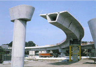
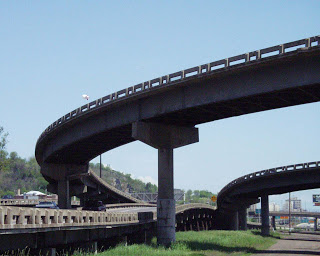
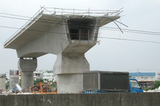
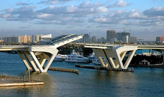
With this increased population there is a simultaneous advancement in our technology and science, we have learned how to effectively utilize the cross-sections of a structure with plastic designs instead of elastic designs. In this way the trends in the type of bridges and flyovers have been changed over the recent past.
Increased spans was a challenging factor in a highway bridge but the factor we should look for is the increased dead weight and then there comes an idea of utilizing the effective area most and removing the un-necessary portion in the section of a bridge and thus there comes the box girder.
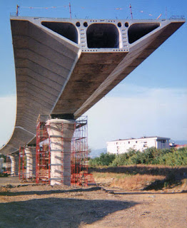
A cellular structure having hollow rectangular section reducing the dead load significantly and thus ensuring greater span and economy.
Structural Section forming a hollow rectangle
Or
Bridge span having top and bottom slabs monolithic with intermediate webs / walls forming one or more rectangular voids
A typical box girder bridge is comprised of top and bottom concrete slabs connected by a series of vertical bridge stems usually called webs that might be inclined or vertical as desired.
A box girder is formed when two web plates are joined by a common flange at both the top and bottom. The closed cell which is formed has a much greater torsional stiffness and strength than an open section and it is this feature which is the usual reason for choosing a box girder configuration.
The box girder consists of concrete, steel or a combination of both. Most of modern elevated structures are built on the basis of the box grider bridge.
The spanning of bridges started with simple slabs. As the spans increased, the design depth of slab is also increased. It is known that material near centre of gravity contributes very little for flexure and hence can be removed. This leads to beam and slab systems. The reinforcement in bottom bulb of beam provided capacity for tensile forces and top slab concrete, the capacity to resist the compression. They formed a couple to resist flexure.
As the width of slab is increased more number of longitudinal girders are required resulting in reduction of stiffness of beams in transverse direction and relatively high transverse curvature. The webs of beams get opened out spreading radially from top slab. Under high transverse bending these will no longer be in their original position. To keep it in their original position the bulbs at bottom should be tied together which in-turn leads to evolution of box girder. Long spans with wider decks and eccentric loading on cross-section will suffer in curvature in longitudinal and transverse direction causing heavy distortion of cross-section. Hence the bridges should have high torsional rigidity in order to resist the distortion of cross-section deck to a minimum.
Like Us on Facebook!
Accordingly box girders are more suitable for larger spans and wider decks, box girders are to be suitable cross-section. They are elegant and slender. Economy and aesthetics further lead to evolution of cantilevers in top flanges and inclined webs in external cells of box girder. The dimension of cell could be controlled by prestressing.
Subscribe Us on YouTube!
As the span and width increases the beams and bottom slabs are to be tied to keep the geometry which in turn leads to evolution box girder.
Any eccentric load will cause high torsional stresses which will be counter acted by the box section. The analysis of such sections are more complicated due combination of flexure, shear, torsion, distortion. But it is more efficient cross-section. It is used for larger spans with wide cross-section. It can be used for spans up to 150m depending upon the construction methods. Cantilever method of construction is preferred most.

