Saad Iqbal | 🗓️Modified: December 25, 2015 | ⏳Read Time: 3 min | 👁Post Views: 989
The algebraic sum of the vertical forces at any section of a beam to the right or left of the section is known as shear force. It is briefly written as S.F.
The algebraic sum of the moments of all the forces acting to the right or left of the section is known as bending moment. It is written as B.M.
 |
| Shear Force and Bending Moment Diagram |
The members of rigid frames and beams may be subjected to shear forces and bending moments as well as axial forces under the action of external loads.
The determination of these internal forces and moments (stress resultants) is necessary for the design of internal forces and moments that may develop in beams and the members of plane frames, under the action of coplanar systems of external forces and couples.
Beams are structural members designed to support loadings applied perpendicular to their axes.
In general, they are long and straight and have a constant cross-sectional area. The actual design of a beam requires a detailed knowledge of the variation of the internal shear force designated by V and bending moment designated by M acting at each point along the axis of the beam.
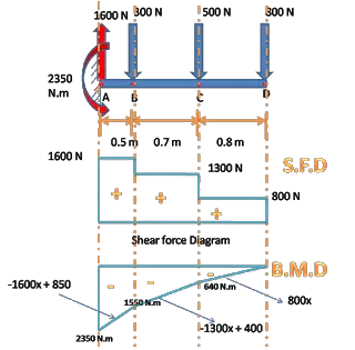
A shear force diagram is one which shows the variation of the shear force along the length of the beam. And a bending moment diagram is one which shows the variation of the bending moment along the length of the beam.
How the Shear Force and Bending Moment Diagram is Drawn
Shear force and bending Moment Diagram is drawn by the method of Sections, in which a section is cut at various distances from the supports to find the internal shear and bending moment at that section. In such a way along the length of the member the forces are known and are then plotted on a graph as shown in the above graph.
To know more about how to draw shear force and bending moment proceed to


